
One-Stop Global Solar Module Mounting Structure Supplier
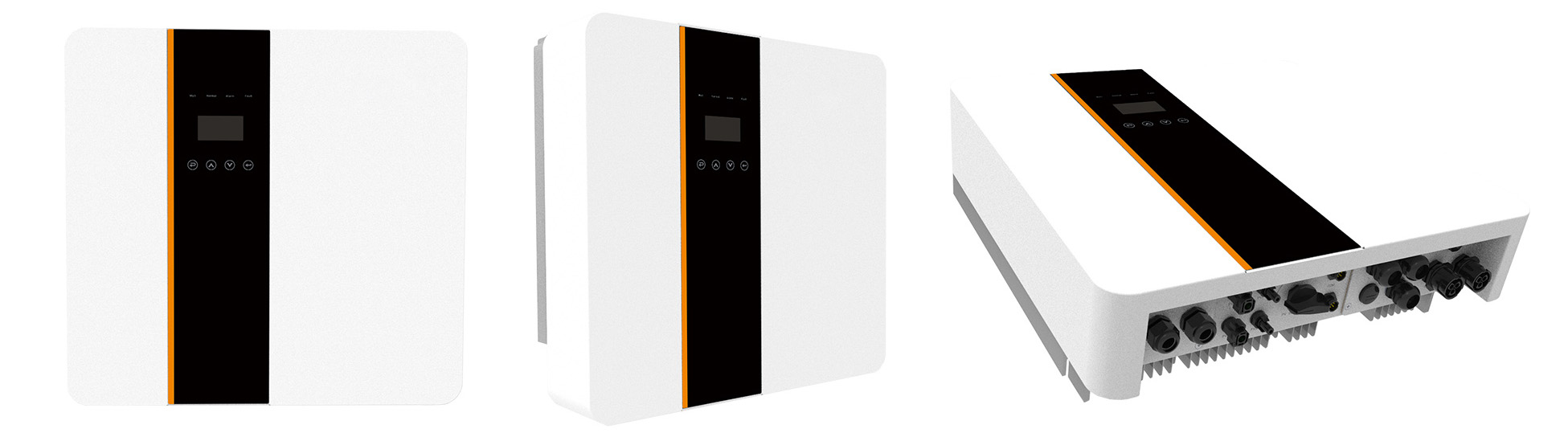
A solar photovoltaic inverter is a power regulation device built on semiconductor devices, and its core function lies in converting direct current electrical energy into alternating current electrical energy. Its typical structure consists of two parts: the boost circuit and the inverter bridge circuit. The boost circuit is responsible for raising the DC voltage generated by the solar cell to the level required for inverter output control. The inverter bridge circuit equivalently converts the boosted DC voltage into an AC voltage that conforms to the frequency of the mains power supply.
This device is also known as a power regulator. In photovoltaic power generation systems, they can be classified into two types based on application scenarios: off-grid type and grid-connected type. According to the waveform modulation method, it includes square wave inverters, step wave inverters, sine wave inverters and combined three-phase inverters. For dedicated inverters for grid-connected systems, they can be further classified into transformer-equipped inverters and transformer-free inverters based on whether they are equipped with transformers or not.
The core performance parameters of solar photovoltaic inverters are as follows:
1. Rated output voltage
Within the allowable fluctuation range of the specified input DC voltage, the photovoltaic inverter should be capable of outputting the rated voltage value. Generally, the rated output for single-phase is 220V and for three-phase is 380V. The voltage fluctuation deviation is specified as follows:
• During steady-state operation, the voltage fluctuation deviation usually does not exceed ±5% of the rated value.
• When the load suddenly changes, the voltage deviation shall not exceed ±10% of the rated value.
• Under normal working conditions, the unbalance degree of the three-phase voltage output by the inverter should be ≤8%.
• The distortion requirements for the output AC voltage waveform (sine wave) are as follows: three-phase output ≤5%, single-phase output ≤10%.
• Under normal operating conditions, the frequency deviation of the AC voltage output by the inverter should be ≤1%. According to the national standard GB/T 19064-2003, the output voltage frequency range is from 49Hz to 51Hz.
2. Load power factor
This parameter characterizes the inverter's ability to drive inductive or capacitive loads. Under the condition of outputting a sine wave, the load power factor is usually set between 0.7 and 0.9, with the rated value generally being 0.9. Under the premise that the load power is determined, if the power factor of the inverter is low, its capacity configuration needs to be increased, resulting in an increase in cost. At the same time, as the apparent power of the system's AC loop increases and the loop current rises, it will inevitably lead to an increase in losses and a reduction in the overall efficiency of the system.
3. Rated output current and rated output capacity
• The rated output current refers to the rated current value that the inverter can output within the specified load power factor range, with the unit being amperes (A).
• The rated output capacity refers to the product of the rated output voltage and the rated output current of the inverter when the output power factor is 1 (i.e., for pure resistive loads), with units of kilovolt-amperes (kVA) or kilowatts (kW).


 IPv6 network supported
leave a message
Scan to wechat :

 English